Calculating the exact steady-state heat loss of an individual room is the fundamental starting point of professional hydronic heating design. Whether you are replacing a single radiator, planning a home extension, or designing a whole-house low-temperature heat pump retrofit, accurate room-by-room calculations ensure every space reaches its design comfort temperature without wasting energy or inflating installation costs.
Historically, plumbers relied on simplistic “rules of thumb” (such as multiplying room floor area by arbitrary BTU or Watt factors). However, modern building physics and rigorous standards—such as BS EN 12831 in the UK/Europe and ACCA Manual J in North America—demand a precise heat balance accounting for composite wall assemblies, window U-values, ceiling boundaries, and convective air changes.
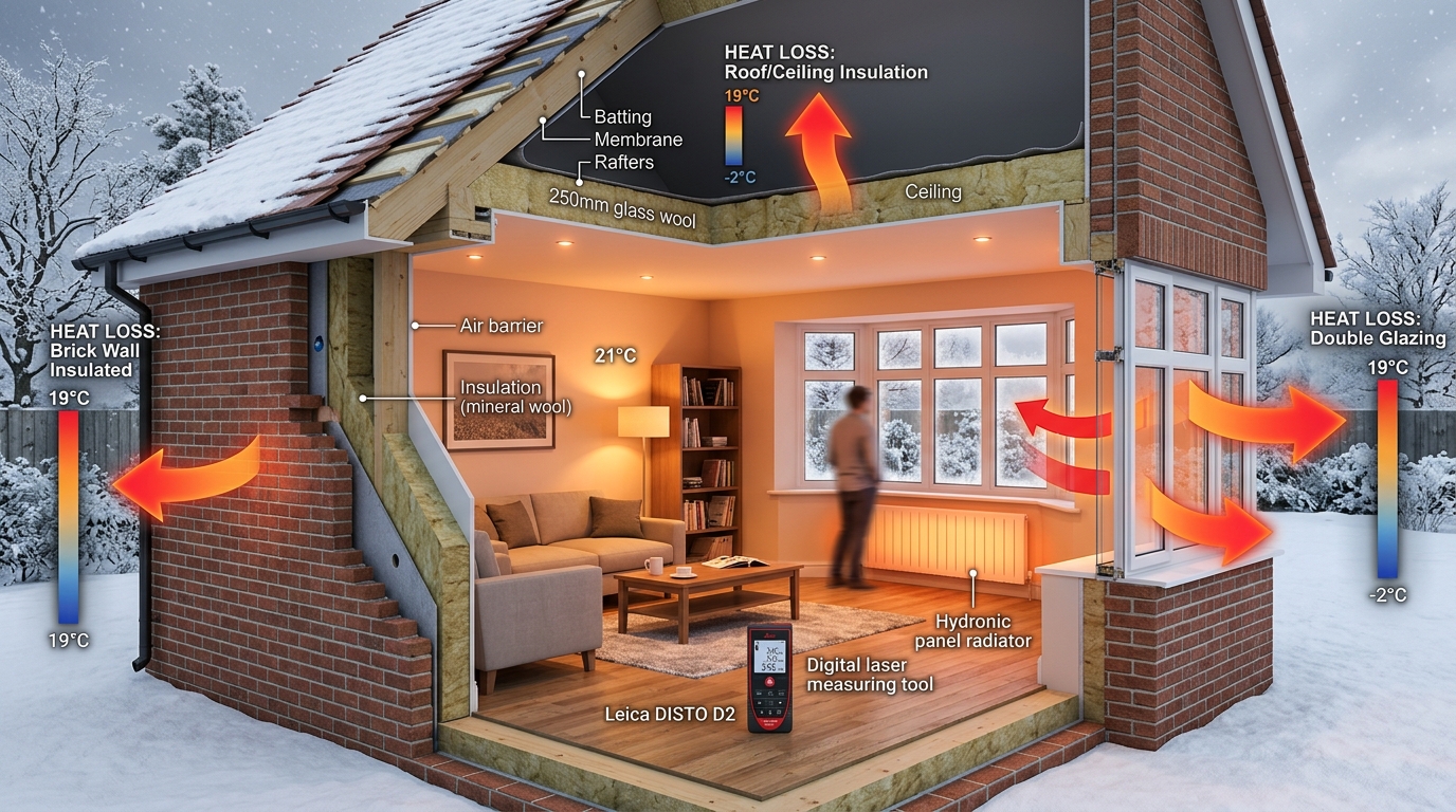
1. The Core Physics of Room Heat Loss
Under steady-state thermodynamic conditions, the total rate of heat energy escaping from a room (Q_total, measured in Watts) equals the sum of three distinct physical transport mechanisms:
Q_total = Q_fabric + Q_ventilation + Q_thermal_bridge
Where:
- Q_fabric (Conductive Transmission Loss): Heat conducting through solid building envelope elements (external walls, windows, external doors, roof ceilings, and ground floors).
- Q_ventilation (Convective Air Infiltration Loss): Heat required to warm cold outdoor air entering through draughts, window trickle vents, chimneys, and background permeability.
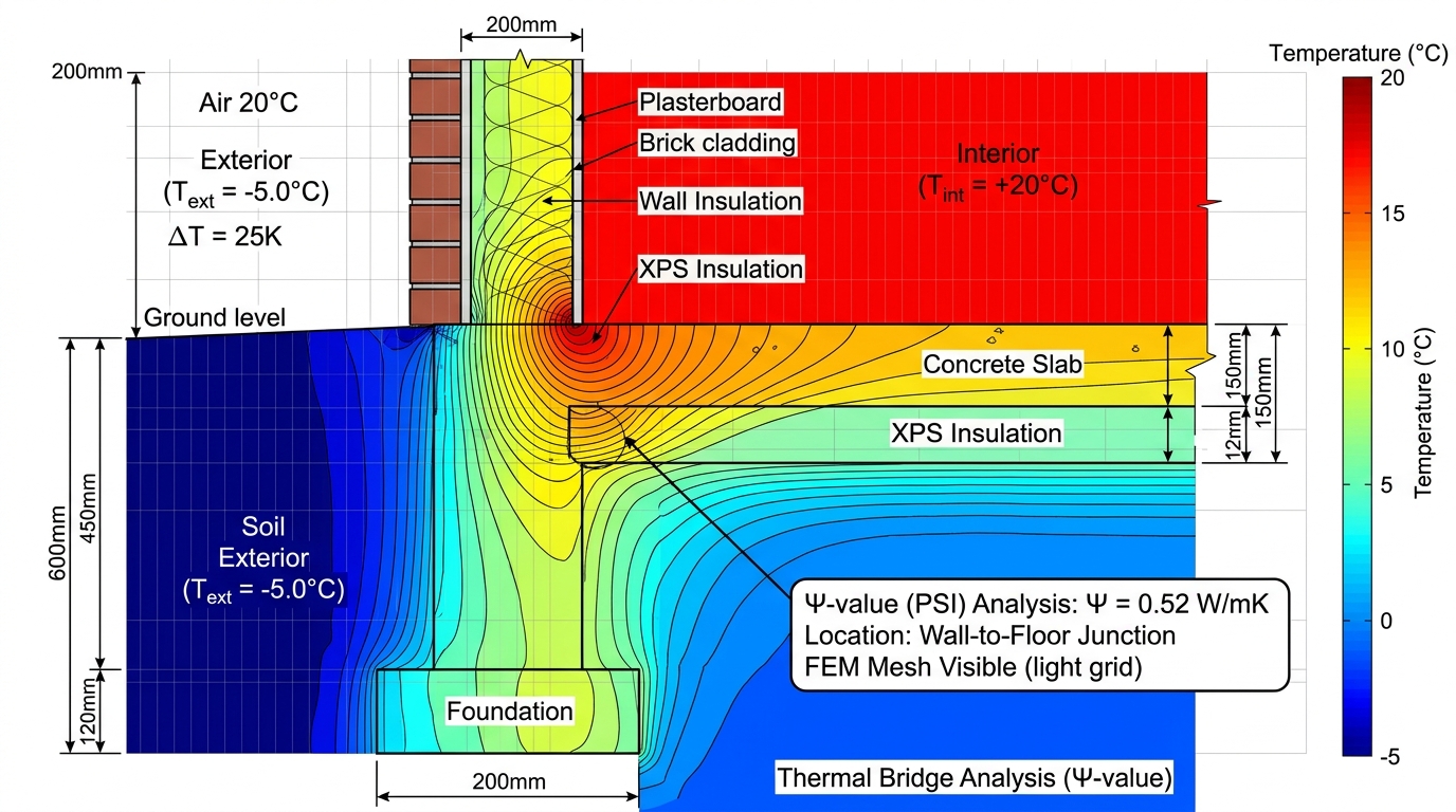
- Q_thermal_bridge (Linear Thermal Bridging Loss): Geometric and structural heat escaping through corners, window reveals, and wall-to-floor junctions where insulation is interrupted.
2. Calculating Fabric Conduction (Q_fabric)
Conductive heat flow through any building element is governed by Fourier’s law of thermal conduction. In building engineering, this is simplified into the standard U-value formula:
Q_fabric = Σ (U × A × ΔT)
Where:
- U (Thermal Transmittance): The rate of heat transfer through 1 m² of the element per degree Kelvin temperature difference (W/m²K).
- A (Net Surface Area): The measured surface area of the element in square metres (m²).
- ΔT (Design Temperature Differential): The difference between internal comfort design temperature (T_int) and the winter outside design temperature (T_ext).
Identifying Boundary Exposure Factors (b_u)
Not all room boundaries lose heat directly to the outside air:
- External Walls / Windows / Roofs: Directly exposed to ambient winter air (ΔT = T_int - T_ext).
- Internal Partition Walls (Heated Adjacent Room): When both rooms are at identical temperatures (e.g. 21°C living room next to 21°C dining room), ΔT = 0, resulting in zero heat loss.
- Internal Partition Walls (Unheated Adjacent Space): When a room borders an unheated garage, cellar, or ventilated loft, apply a temperature reduction factor (b_u between 0.5 and 0.8) to account for the buffer zone effect:
Q_partition = U × A × (T_int - T_ext) × b_u
3. Calculating Air Infiltration & Ventilation Loss (Q_vent)
Even well-insulated rooms experience continuous air exchange. When warm room air leaks out through gaps and cold outdoor air enters, energy is required to continuously heat this fresh air volume up to the target room temperature:
Q_vent = 0.33 × n × V × ΔT
Where:
- 0.33: The volumetric heat capacity of air in metric units (Wh/m³K), derived from density × specific heat capacity / 3600.
- n (Air Changes per Hour - ACH): The number of times the total room air volume is replaced every hour.
- V (Internal Room Air Volume): Calculated as Length × Width × Ceiling Height in cubic metres (m³).
- ΔT: Design temperature difference (T_int - T_ext).
Standard Air Change Rate (ACH) Benchmarks
- Pre-1980s Draughty Rooms (Unsealed sash windows, open chimney): 1.5 to 2.0 ACH
- Standard Modern Rooms (Double glazing, trickle vents): 0.8 to 1.0 ACH
- Airtight New Builds (Mechanical ventilation / MVHR): 0.3 to 0.5 ACH
4. Internal Design Temperatures & CIBSE Comfort Standards
Under CIBSE Guide A and BS EN 12831, internal design temperatures reflect human metabolic activity and clothing insulation:
| Room Type | Recommended Internal Temp | Design ACH | Engineering Rationale |
|---|---|---|---|
| Living Room / Lounge | 21°C (70°F) | 1.0 – 1.5 | Sedentary evening relaxation requires higher ambient thermal comfort. |
| Dining Room | 21°C (70°F) | 1.0 – 1.5 | Seated dining comfort with moderate occupancy gains. |
| Bedrooms | 18°C (64°F) | 0.5 – 1.0 | Circadian sleep hygiene under insulated bedding requires lower ambient air temp. |
| Bathrooms & En-suites | 22°C – 24°C (75°F) | 2.0 – 3.0 | Prevents post-shower thermal shock and rapid evaporative skin cooling. |
| Kitchen | 18°C (64°F) | 1.5 – 2.0 | Cooking appliance heat gains supplement space heating. |
| Hallways & Corridors | 18°C (64°F) | 1.5 – 2.0 | Transitional circulation spaces with frequent external door openings. |
5. In-Depth Worked Calculation: 1930s Living Room
To understand how these formulas apply in practice, let us calculate the heat loss for a realistic living room in a 1930s semi-detached house located near Birmingham, UK.
Step 1: Survey Data & Dimensions
- Location: Birmingham (CIBSE 99.6% Winter Design Temp: T_ext = -3.4°C)
- Room Setpoint: Living Room (T_int = 21.0°C)
- Temperature Difference: ΔT = 21.0 - (-3.4) = 24.4 K
- Room Dimensions: 4.8 m (Length) × 4.2 m (Width) × 2.6 m (Height)
- Floor Area: A_floor = 4.8 × 4.2 = 20.16 m²
- Room Volume: V = 20.16 × 2.6 = 52.42 m³
Step 2: Boundary Surfaces & Net Areas
- Front External Wall (Solid 9” uninsulated brick with bay):
- Gross Area: 4.8 m × 2.6 m = 12.48 m²
- Bay Window Area (Older double glazing): 4.20 m²
- Net Brickwork Area: 12.48 - 4.20 = 8.28 m² (U = 2.10 W/m²K)
- Window Area: 4.20 m² (U = 2.80 W/m²K)
- Flank External Wall (Exposed gable cavity wall):
- Area: 4.2 m × 2.6 m = 10.92 m² (U = 1.50 W/m²K)
- Suspended Timber Floor (Uninsulated over ventilated crawlspace):
- Area: 20.16 m² (U = 0.70 W/m²K, b_u = 0.8, ΔT_eff = 19.5 K)
- Ceiling to Heated Bedroom Above:
- ΔT = 21°C - 18°C = 3.0 K, U = 1.6 W/m²K, Area: 20.16 m²
- Ventilation / Infiltration:
- Older double glazed windows with open decorative fireplace: n = 1.2 ACH
Step 3: Heat Loss Computation
- Q_wall_front = 8.28 m² × 2.10 × 24.4 = 424.3 W
- Q_window = 4.20 m² × 2.80 × 24.4 = 286.9 W
- Q_wall_flank = 10.92 m² × 1.50 × 24.4 = 399.7 W
- Q_floor = 20.16 m² × 0.70 × 19.5 = 275.2 W
- Q_ceiling = 20.16 m² × 1.60 × 3.0 = 96.8 W
- Q_fabric_subtotal = 1,482.9 Watts
- Q_ventilation = 0.33 × 1.2 × 52.42 m³ × 24.4 = 506.5 Watts
- Q_thermal_bridge (10% allowance) = 148.3 Watts
Total Room Heat Loss = 1,482.9 + 506.5 + 148.3 = 2,137.7 Watts (7,294 BTU/hr)
Specific Load Summary:
- Specific Floor Load: 2,137.7 W / 20.16 m² = 106.0 W/m²
- Specific Volume Load: 2,137.7 W / 52.42 m³ = 40.8 W/m³
6. Sizing Radiators for Boilers vs. Heat Pumps
Once room heat loss (2,138 W) is established, you must select the radiator panel based on the system’s operating flow and return temperatures:
Operating at ΔT50 (Standard Gas Boiler)
- Flow: 75°C, Return: 65°C, Room: 21°C -> Mean Water Temp: 70°C -> ΔT = 49 K ≈ ΔT50.
- Required Catalog Radiator Capacity: 2,138 Watts.
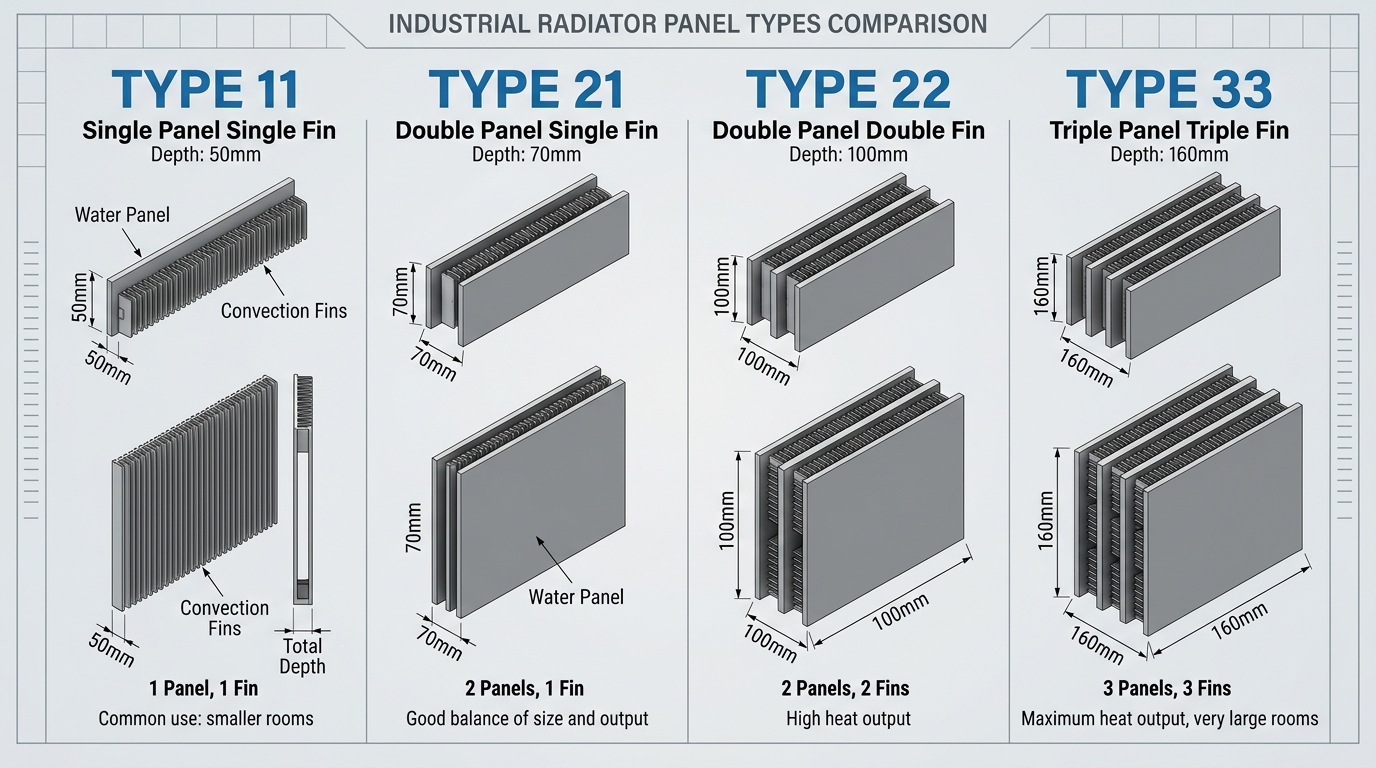
- Selected Emitter: A single Type 22 (600mm H × 1200mm L) radiator delivering approx 2,160 W at ΔT50.
Operating at ΔT30 (Low-Temperature Heat Pump)
- Flow: 50°C, Return: 40°C, Room: 21°C -> Mean Water Temp: 45°C -> ΔT = 24 K ≈ ΔT25–ΔT30.
- BS EN 442 Exponent Factor: F = (24 / 50)^1.30 = 0.384.
- Required Catalog Rated Capacity at ΔT50: 2,138 W / 0.384 = 5,567 Watts.
- Selected Emitters: Two Type 22 (600mm H × 1600mm L) radiators (each rated 2,880 W at ΔT50), positioned under the bay window and on the flank wall.
7. Top 7 Room Sizing Mistakes to Avoid
- Using Square Footage Rules of Thumb: Generic BTU/sq ft charts ignore whether the wall is solid 1900 brick or 2024 cavity insulation, leading to severe under- or over-sizing.
- Ignoring Window Opening Deductions: Failing to subtract window glass area from the gross external wall area double-counts the masonry wall surface.
- Forgetting Chimney Stack Draughts: An unsealed open fireplace draws continuous warm air out of the room at over 40 m³/hr, doubling infiltration heat loss.
- Neglecting Ceiling Heat Transfer to Cooler Bedrooms: Rooms with different setpoints (e.g. 21°C living room below an 18°C bedroom) conduct heat across internal timber joists.
- Assuming Radiator Output Scales Linearly: Due to natural convective slowing, a radiator operating at half the temperature difference produces only 38%–51% of its catalog heat output.
- Double Counting Party Walls: Party walls adjoining heated neighbouring properties lose zero heat to the outdoors because ΔT ≈ 0.
- Neglecting Available Wall Length: Sizing a radiator without verifying the physical window sill width and height can lead to awkward installation clashes.
8. Interactive Tools & Next Steps
To calculate your own room heat loss and size your radiators using real-time interactive engineering engines, explore our dedicated calculation suite:
- Room Heat Loss Calculator: Precision single-room calculation with interactive 2D room boundary visualizer.
- Radiator Size Calculator: BS EN 442 radiator sizing across Type 11, 21, 22, and 33 panels for ΔT50 and ΔT30.
- Room-by-Room Schedule Generator: Aggregate all rooms across your property into an exportable MCS-compliant CSV schedule.
- U-Value Calculator: Build composite multi-layer wall, floor, and roof assemblies conforming to BS EN ISO 6946.