Accurately calculating the thermal heat load of a residential building is the single most important step in designing any HVAC system. In the heating and air conditioning industry, professionals encounter two primary calculation approaches: comprehensive engineering standards—such as ACCA Manual J (the North American standard) and BS EN 12831 (the European standard)—and streamlined, steady-state building physics models (like the engines powering modern interactive calculation software).
Understanding the differences in mathematical complexity, input requirements, calculation time, and resultant accuracy is essential for heating engineers, heat pump installers, architects, and energy assessors.

1. What is ACCA Manual J?
Developed by the Air Conditioning Contractors of America (ACCA) and approved by ANSI, Manual J (Residential Load Calculation) is the legal standard of care for residential HVAC load sizing across the United States and Canada (codified in the International Residential Code / IRC Section M1401.3).
Manual J performs an exhaustive, room-by-room calculation that determines two separate peak loads:
- Winter Heating Load (BTU/hr or kW): The maximum steady-state rate of heat loss through building assemblies during design winter temperatures at night (ignoring internal and solar gains).
- Summer Cooling Load (Sensible & Latent, in BTU/hr or Tons): The maximum rate of heat gain from outdoor ambient air, solar radiation through windows, internal heat from appliances and lighting, and moisture removal (latent humidity load from occupants and infiltration).
Key Features of Manual J:
- Solar Heat Gain Coefficients (SHGC): Calculates hourly solar radiation angles and glass overhang shading factors for every window orientation.
- Duct Thermal Losses (Manual D Integration): Accounts for heat lost through supply and return ductwork running through unconditioned, freezing attics or hot crawlspaces.
- Internal Heat Gain Schedules: Adds specific sensible and latent BTU contributions for human occupants (230 BTU/hr sensible per person) and kitchen appliances.
2. What is BS EN 12831?
In the United Kingdom and European Union, the statutory standard for heating sizing is BS EN 12831 (Energy Performance of Buildings - Method for Calculation of the Design Heat Load). Unlike Manual J (which emphasizes summer air conditioning loads), EN 12831 is laser-focused on winter peak heating loads for hydronic radiator, underfloor, and heat pump systems.
Key Features of BS EN 12831:
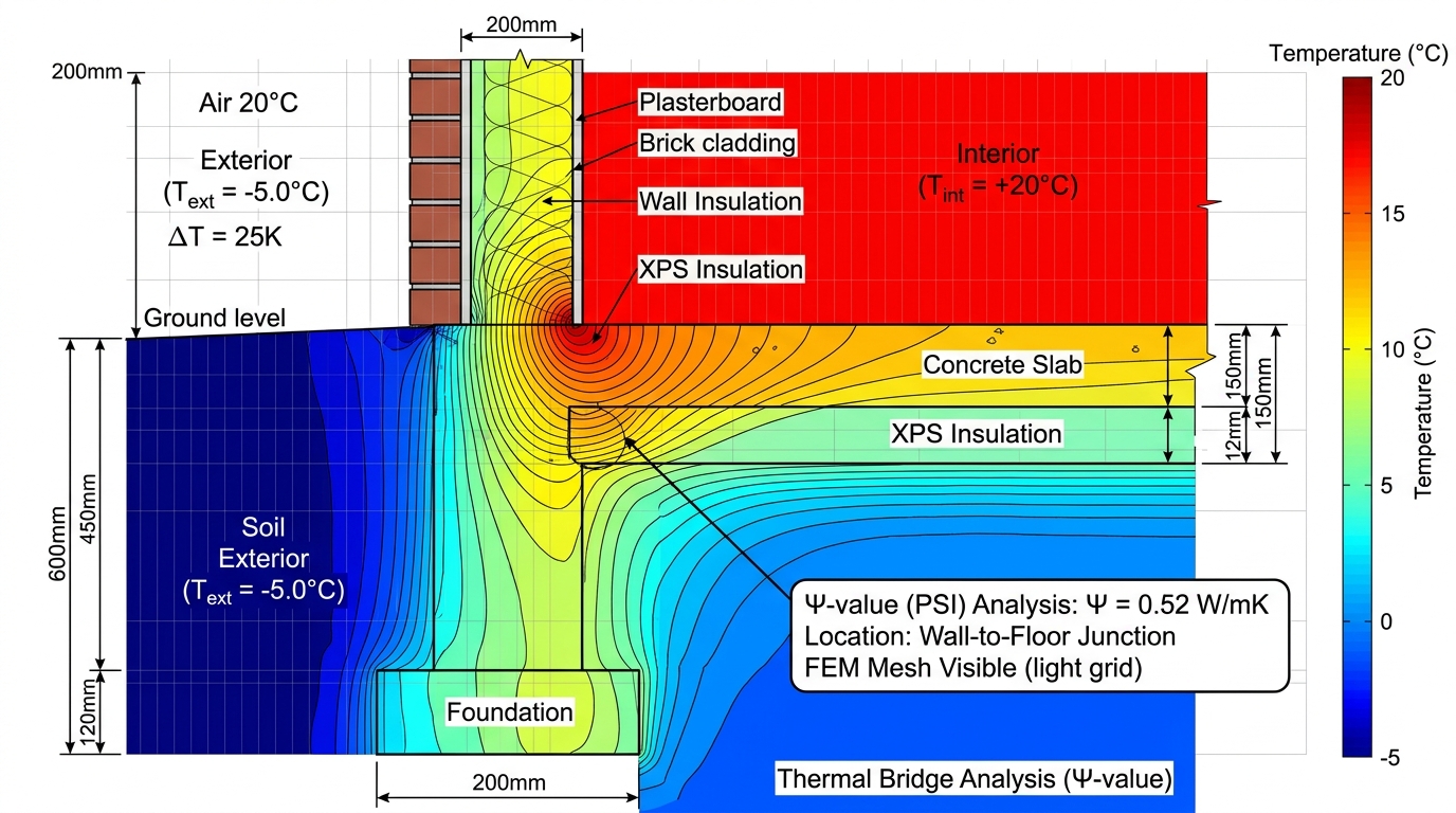
- Fabric Transmission (Transmission Loss): Sums conductive losses through external walls, roofs, ground slabs, and internal partitions to unheated zones using ISO 6946 U-values and buffer temperature factors (b_u).
- Convective Ventilation (Ventilation Loss): Computes minimum hygienic air exchange rates and natural wind-driven background infiltration (Q = 0.33 × n × V × ΔT).
- Reheat Capacity Allowance (f_rh): Adds a standardized reheating boost (in W/m²) for intermittently operated heating systems that setback temperatures overnight, ensuring the system can recover to comfort temperature within 1 to 2 hours.
3. Comparison Matrix: Standards vs. Simplified Heat Loss Models
To understand when each methodology should be used, examine this comparative breakdown:
| Feature / Metric | “Rule of Thumb” Sizing | Simplified Physics Model (This Tool) | Full BS EN 12831 Audit | Full ACCA Manual J (8th Ed) |
|---|---|---|---|---|
| Calculation Time | 30 Seconds | 2 to 5 Minutes | 1 to 3 Hours | 2 to 4 Hours |
| Accuracy vs Reality | ±50%–100% (Dangerous) | ±5%–8% (High Precision) | ±2%–4% (Gold Standard) | ±2%–4% (Gold Standard) |
| Required Inputs | Floor area only | Room dims, U-values, glazing, ACH | Full architectural survey, U-values | Full window SHGC, duct R-values, shading |
| Thermal Bridging? | No | Yes (Statistical ΔU_tb factor) | Yes (Full Ψ · L calculation) | Yes (Framing factors) |
| Delta T Sizing? | Assumes 75°C boiler | Full BS EN 442 (ΔT20–ΔT50) | Full hydronic curve | Sensible CFM airflow |
| Regulatory Fit | Prohibited | Initial Sizing & Retrofit Audits | MCS / UK Part L Compliance | US Permitting / Code Sign-Off |
4. The Dangers of “Rule of Thumb” HVAC Sizing
For decades, non-technical contractors sized equipment using archaic rules of thumb:
- “500 square feet per ton of cooling.”
- “30 to 40 BTU per square foot of floor space.”
- “50 Watts per cubic metre.”
Why Rules of Thumb Cause Catastrophic Failure in Modern Homes:
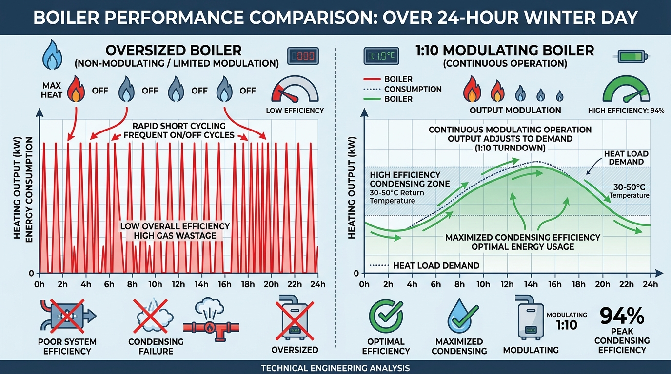
- Gross Equipment Oversizing: A 1970s uninsulated house might require 80 W/m², while a modern 2024 Part L or IECC home requires only 30 W/m². Applying an arbitrary 70 W/m² rule of thumb to a new home results in an HVAC system that is 130% oversized.
- Short-Cycling & Condensing Failure: Oversized gas boilers cycle on and off constantly in mild weather, failing to condense flue gases and wasting 10%–15% in gas fuel bills.
- Severe Heat Pump SCOP Degradation: An oversized heat pump cannot throttle down to low compressor speeds during mild autumn and spring days. Continuous cycling drops seasonal SCOP from 4.0 down to 2.8, doubling winter electric bills.
- Poor Summer Dehumidification: An oversized air conditioning compressor cools the air too rapidly, shutting off before it has run long enough to pull latent moisture from the air, creating a cold, clammy indoor environment prone to mold.
5. How Simplified Calculation Engines Deliver 95%+ Accuracy
Modern online calculators (such as the engines on this platform) use the exact same fundamental thermodynamic equations (Q = Σ U × A × ΔT and Q = 0.33 × n × V × ΔT) as full Manual J and EN 12831 software suites.
Where Simplified Calculators Streamline the Workflow:
- Pre-Computed Component Assemblies: Instead of requiring manual entry of 15 individual sub-layers for a cavity wall, simplified calculators provide validated composite U-values conforming to BS EN ISO 6946 (e.g. 0.28 W/m²K for standard cavity brickwork).
- Standardized Air Infiltration Benchmarks: Users select verified air change rates (e.g. 0.8 ACH for double-glazed homes) rather than calculating complex crack-length aerodynamic equations.
- Global Meteorological Climatic Databases: Automatic lookup of official 99.6% winter outdoor design temperatures (CIBSE Guide A and ASHRAE Fundamentals) for over 80 cities worldwide.
6. When to Use a Simplified Tool vs. a Full Manual J / EN 12831 Audit
Use an Interactive Simplified Calculator When:
- Performing initial feasibility assessments for a heat pump or boiler upgrade.
- Sizing replacement radiators in an existing room or home extension.
- Evaluating the return on investment (ROI) of adding cavity wall or loft insulation.
- Estimating annual seasonal fuel costs and electricity consumption across different heating technologies.
Commission a Full Manual J or MCS EN 12831 Formal Survey When:
- Submitting official engineering drawings to building control for new construction permitting.
- Applying for government clean heat grants (e.g. UK Boiler Upgrade Scheme / MCS certification).
- Designing complex ducted central air conditioning systems requiring Manual D duct layout and Manual S equipment selection.
7. Top 5 HVAC Sizing Mistakes Across All Methodologies
- Adding Arbitrary 20%–30% Safety Buffers: Compounding safety margins onto an already conservative 99.6% design day calculation results in severe system oversizing.
- Ignoring Unconditioned Duct Heat Losses: In ducted US systems, uninsulated sheet metal ducts running through a freezing attic can lose 20% to 30% of total furnace heat output before air reaches the living room registers.
- Double-Counting Internal Gains in Winter Heating Calculations: Sizing heating equipment based on the assumption that appliances and lights are always running can leave the house cold on freezing winter mornings when the home is unoccupied.
- Misjudging Window Solar Heat Gain Coefficients (SHGC): In cooling-dominated climates, failing to account for Low-E solar control coatings overestimates air conditioning load by multiple tons.
- Neglecting Altitude Lapse Rate Corrections: Using sea-level meteorological data for a home located 300 metres up in the hills results in an undersized heating system during winter frosts.
8. Interactive Calculation Suite
Calculate your building’s thermal performance online with precision engineering tools:
- Room Heat Loss Calculator: Precision single-room calculation conforming to BS EN 12831 principles.
- Whole House Calculator: Whole-building peak kW load and annual energy demand engine.
- Radiator Size Calculator: Sizing engine with official BS EN 442 Delta T correction factors.
- Heat Pump Size Calculator: Size MCS-compliant ASHP/GSHP systems and optimize seasonal SCOP efficiency.