Thermal transmittance (U-value) and thermal resistance (R-value) are the two fundamental metrics used by architects, building physicists, and HVAC engineers to quantify how easily heat escapes through a building envelope. Whether analyzing an uninsulated Victorian brick wall or specifying a multi-layer Passivhaus timber frame, understanding the mathematical relationship between thermal conductivity (lambda / λ), material thickness (d), surface air films (R_si, R_se), and thermal bridging is essential.
This guide provides a comprehensive breakdown of thermal transmission physics, international unit conversions, multi-layer calculation methodologies under BS EN ISO 6946, and regulatory compliance benchmarks across the UK, Europe, and North America.
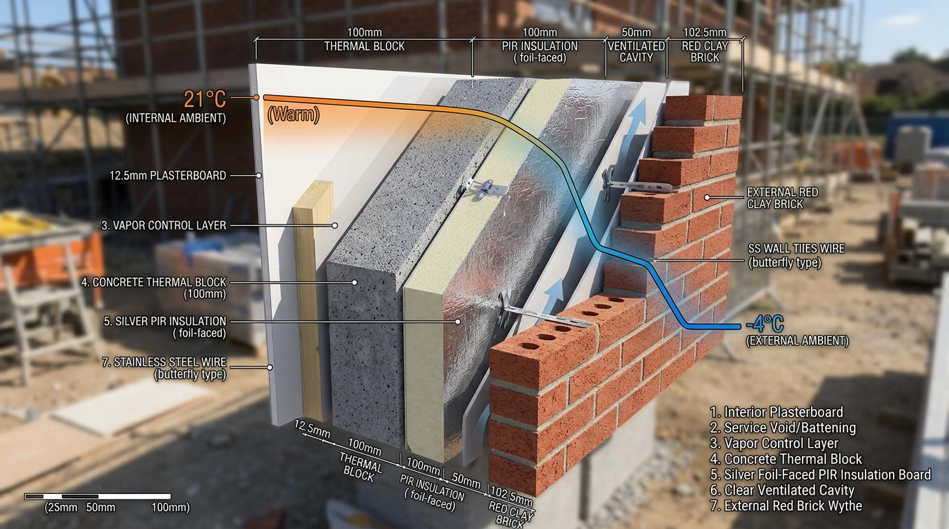
1. Fundamentals: Definitions, Symbols, and Units
To evaluate any building element, three interrelated physical properties must be distinguished:
1. Thermal Conductivity (lambda / λ or k)
- Definition: The intrinsic property of a homogeneous material that measures the rate at which heat conducts through a 1-metre thick slab of the material for a temperature difference of 1 Kelvin.
- Metric Unit: Watts per metre Kelvin (W/mK).
- Key Insight: A lower lambda-value means the material is a better insulator. For example, PIR insulation has lambda = 0.022 W/mK, whereas dense brickwork has lambda = 0.770 W/mK (brick conducts heat 35× faster).
2. Thermal Resistance (R or RSI)
- Definition: The capacity of a specific layer of material of thickness d to resist conductive heat flow: R = d / λ Where d is layer thickness in metres (m) and λ is thermal conductivity (W/mK).
- Metric Unit (RSI): Square metres Kelvin per Watt (m²K/W).
- Imperial Unit (R-value): Hours square-feet Fahrenheit per BTU (h·ft²·°F/BTU).
- Key Insight: A higher R-value means greater thermal resistance and superior insulation.
3. Thermal Transmittance (U-value)
- Definition: The rate of steady-state heat conduction through one square metre of a complete composite building structure per degree Kelvin of temperature difference across its internal and external environments: U = 1 / R_total
- Metric Unit: Watts per square metre Kelvin (W/m²K).
- Imperial Unit: BTU/h·ft²·°F.
- Key Insight: A lower U-value means less heat escapes through the structure.
2. Converting Between Metric (RSI / U) and Imperial (R / U) Units
Because North American construction relies on Imperial R-values while UK and European building codes use Metric U-values and RSI, engineers frequently require exact conversion formulas:
- Imperial R = Metric RSI × 5.678263
- Metric RSI = Imperial R / 5.678263
- Metric U (W/m²K) = 1 / Metric RSI = 5.678263 / Imperial R
- Imperial U (BTU/h·ft²·°F) = Metric U × 0.176110
Quick Reference Conversion Matrix:
| Target Performance Level | Imperial R-Value | Metric RSI (m²K/W) | Metric U-Value (W/m²K) | Imperial U-Value |
|---|---|---|---|---|
| Uninsulated Solid Brick Wall | R-2.7 | 0.48 | 2.10 W/m²K | 0.370 |
| 1970s Cavity Wall (Uninsulated) | R-3.8 | 0.67 | 1.50 W/m²K | 0.264 |
| 1990s Part L Cavity (50mm Foam) | R-12.6 | 2.22 | 0.45 W/m²K | 0.079 |
| UK Part L 2021 Wall Standard | R-31.5 | 5.56 | 0.18 W/m²K | 0.032 |
| UK Part L 2021 Roof Standard | R-51.6 | 9.09 | 0.11 W/m²K | 0.019 |
| Passivhaus Certified Wall | R-56.8 | 10.00 | 0.10 W/m²K | 0.018 |
3. How to Calculate Composite U-Values (BS EN ISO 6946)
Under BS EN ISO 6946, the total thermal resistance of any flat multi-layer building assembly (R_total) is the sum of the thermal resistances of every individual material layer plus the internal and external boundary surface air film resistances:
R_total = R_si + Σ (d_i / λ_i) + R_g + R_se
Where:
- R_si (Internal Surface Resistance): Thermal resistance of the stagnant indoor boundary air film:
- Horizontal Heat Flow (Walls): R_si = 0.13 m²K/W
- Upward Heat Flow (Flat Roofs / Ceilings): R_si = 0.10 m²K/W
- Downward Heat Flow (Floors): R_si = 0.17 m²K/W
- R_se (External Surface Resistance): Thermal resistance of the wind-exposed outdoor surface air layer:
- All external orientations: R_se = 0.04 m²K/W
- R_g (Air Cavity Resistance): Thermal resistance of an unventilated or slightly ventilated air gap (typically 0.16 to 0.18 m²K/W for a 50mm sealed cavity).
- Composite U-Value: U = 1 / R_total
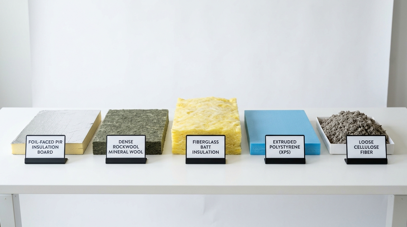
4. Insulation Materials Comparison & Thermal Conductivity Matrix
Different insulation materials achieve their thermal resistance through different microscopic structures:
| Insulation Material | Thermal Conductivity (λ) | Imperial R / inch | Moisture Resistance | Fire Rating | Best Use Case |
|---|---|---|---|---|---|
| Aerogel Blankets | 0.015 W/mK | R-9.6 / in | High | Class A1 (Non-combustible) | Ultra-slim historic window reveals & balcony thresholds. |
| Polyisocyanurate (PIR / Foil) | 0.022 W/mK | R-6.5 / in | Excellent | Class B (Combustible with retardant) | High-performance walls, warm roofs, and floors where space is limited. |
| Extruded Polystyrene (XPS) | 0.029 W/mK | R-5.0 / in | Waterproof | Class E | Below-grade foundation walls, basement slabs, and inverted roofs. |
| Mineral Wool (Rockwool) | 0.035 W/mK | R-4.0 / in | Breathable | Class A1 (Completely Fireproof) | Timber frame stud infill, acoustic partitions, external rainscreen cladding. |
| Expanded Polystyrene (EPS) | 0.038 W/mK | R-3.8 / in | Moderate | Class E | External Wall Insulation (EWI) render systems. |
| Dense-Pack Cellulose | 0.038 W/mK | R-3.7 / in | Hygroscopic | Class B (Treated borate) | Blown attic floors and retrofit closed stud cavities. |
| Glass Mineral Wool (Fiberglass) | 0.042 W/mK | R-3.3 / in | Permeable | Class A1 | Cost-effective open loft ceiling quilt rolls. |
5. The Law of Diminishing Returns in Thermal Insulation
A widespread misconception among homeowners is that adding 100mm of insulation will save twice as much energy as adding 50mm.
Because heat loss is an inverse function of thermal resistance (Q is proportional to 1/R), the energy savings follow a steep curve of diminishing marginal returns:
ΔQ = Q_initial - Q_new = A × ΔT × (U_old - U_new)
Example: Insulating a 100 m² Solid Brick Wall (U = 2.10 W/m²K, ΔT = 25K)
- Baseline (Uninsulated): Heat Loss = 100 × 2.10 × 25 = 5,250 Watts.
- Adding 50mm PIR Insulation (R_ins = 2.27, U = 0.36): Heat Loss = 100 × 0.36 × 25 = 900 Watts (82.9% heat loss cut! Saves 4,350 Watts).
- Adding 100mm PIR Insulation (R_ins = 4.55, U = 0.20): Heat Loss = 100 × 0.20 × 25 = 500 Watts (90.5% heat loss cut! Saves an extra 400 Watts).
- Adding 200mm PIR Insulation (R_ins = 9.09, U = 0.10): Heat Loss = 100 × 0.10 × 25 = 250 Watts (95.2% heat loss cut! Saves an extra 250 Watts).
Crucial Takeaway: The first 50mm of insulation achieves over 80% of the maximum possible energy savings. Beyond 100mm, further improvements must be balanced against loss of internal room floor space and material costs.
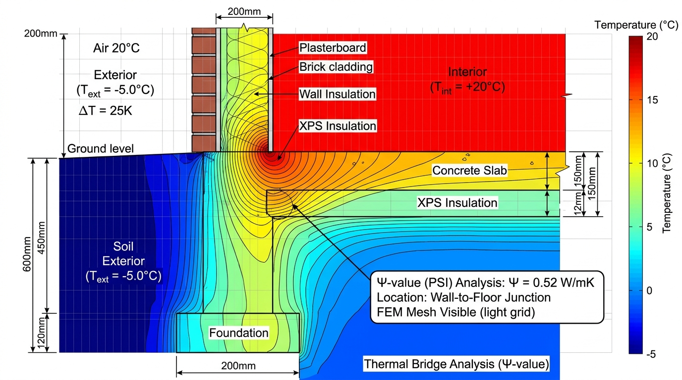
6. Thermal Bridging Corrections & Repeating Bridges
A composite U-value calculation is only as accurate as its thermal bridge modeling:
1. Repeating Thermal Bridges (Bridged Layer Analysis)
When an insulation layer is interrupted at regular intervals by structural framing (such as timber studs in a framed wall or steel purlins in a roof), the layer must be calculated as a composite fraction under ISO 6946 using parallel path upper and lower resistance bounds.
Where timber studs make up approximately 15% of standard 400mm centered framing, timber (lambda = 0.13 W/mK) conducts heat 3.5× faster than mineral wool (lambda = 0.038 W/mK), which degrades nominal insulation performance by 15% to 25%.
2. Non-Repeating Linear Thermal Bridges (Psi-Values / Ψ)
Linear thermal bridges occur at building corners, window reveals, and floor-to-wall junctions. The total heat loss associated with linear bridges is calculated as:
Q_tb = Σ (Ψ × L × ΔT)
Where Ψ (Psi-value, in W/mK) is the linear thermal transmittance and L is the length of the junction in metres.
7. Top 5 U-Value Calculation Errors
- Adding U-Values Together Directly: Mathematical rule: U_total is NOT equal to U_1 + U_2. You must sum resistances (R_total = R_1 + R_2 + …) and invert the total (U = 1 / R_total).
- Forgetting Surface Boundary Air Films: Omitting R_si = 0.13 and R_se = 0.04 leads to a 10%–20% error in uninsulated and thin assembly calculations.
- Ignoring Wood Stud Thermal Bridging: Assuming an entire timber stud wall performs at the nominal R-value of the cavity batt ignores the 15%–20% wood framing area.
- Using Dry Initial Lambda Instead of Declared Lambda: Polyurethane and PIR foam insulations experience slight long-term gas diffusion. Always use aged declared thermal conductivity values.
- Confusing Imperial R-Value with Metric RSI: Entering an Imperial R-value (e.g. R-20) into a metric equation without dividing by 5.678 will distort heat loss calculations by over 500%.
8. Interactive Calculation Suite
Build custom multi-layer assemblies and convert thermal metrics online:
- U-Value Calculator: Build multi-layer walls, roofs, and floors conforming to BS EN ISO 6946 with live temperature gradient visualization.
- R-Value Calculator & Converter: 4-way bidirectional converter between Imperial R, Metric RSI, and U-values.
- Room Heat Loss Calculator: Apply your composite U-values to individual rooms for precision radiator sizing.
- Whole House Calculator: Calculate total building envelope heat loss and seasonal energy consumption.